How do you test a satellite controller before it reaches orbit?
A camera points correctly in an ideal simulation. Add sensor bias and actuator limits, and the code begins answering a more useful question about the spacecraft.
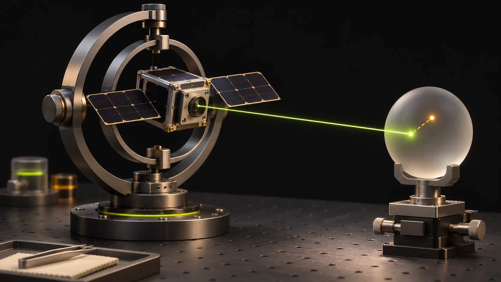
The camera points beautifully in the simulation
A small satellite has found its target. Its camera turns toward Earth, the pointing error falls and the line on the screen settles near zero. That is an encouraging beginning. Now give the simulated sensor a small bias, so every reading is slightly offset. Limit the actuator, the device that turns a control command into a physical action. Change the initial orientation. Can the spacecraft still point where it needs to?
A preprint submitted on 2 November by Patrick McKeen, Niclas Scheuer and Kerri Cahoy presents a modular Python framework for satellite attitude determination and control: estimating which way a satellite points and adjusting that direction. Sensors, control algorithms and hardware models can be exchanged through configuration. The same package also runs in a Raspberry Pi hardware-in-the-loop demonstration, where a real computer participates in the simulated experiment.
One case study models a small satellite with three magnetorquers, devices that interact with Earth's magnetic field, and a reaction wheel that spins to change the spacecraft's orientation. Other cases use different combinations, including thrusters. The authors examine sensor and actuator failures as well as normal operation. This makes the framework interesting for a team choosing hardware: it can compare how a control method behaves when the spacecraft's available actions change.
Source: Satellite-control preprint, submitted 2 November 2026
Keep the spacecraft separate from what it believes
A classroom simulation can make an illuminating mistake: hand the controller the exact orientation stored inside the simulator. The controller then receives knowledge a real sensor would have to estimate. The result may be useful for an idealized experiment, but its meaning changes when it is described as a test of a sensing-and-control system.
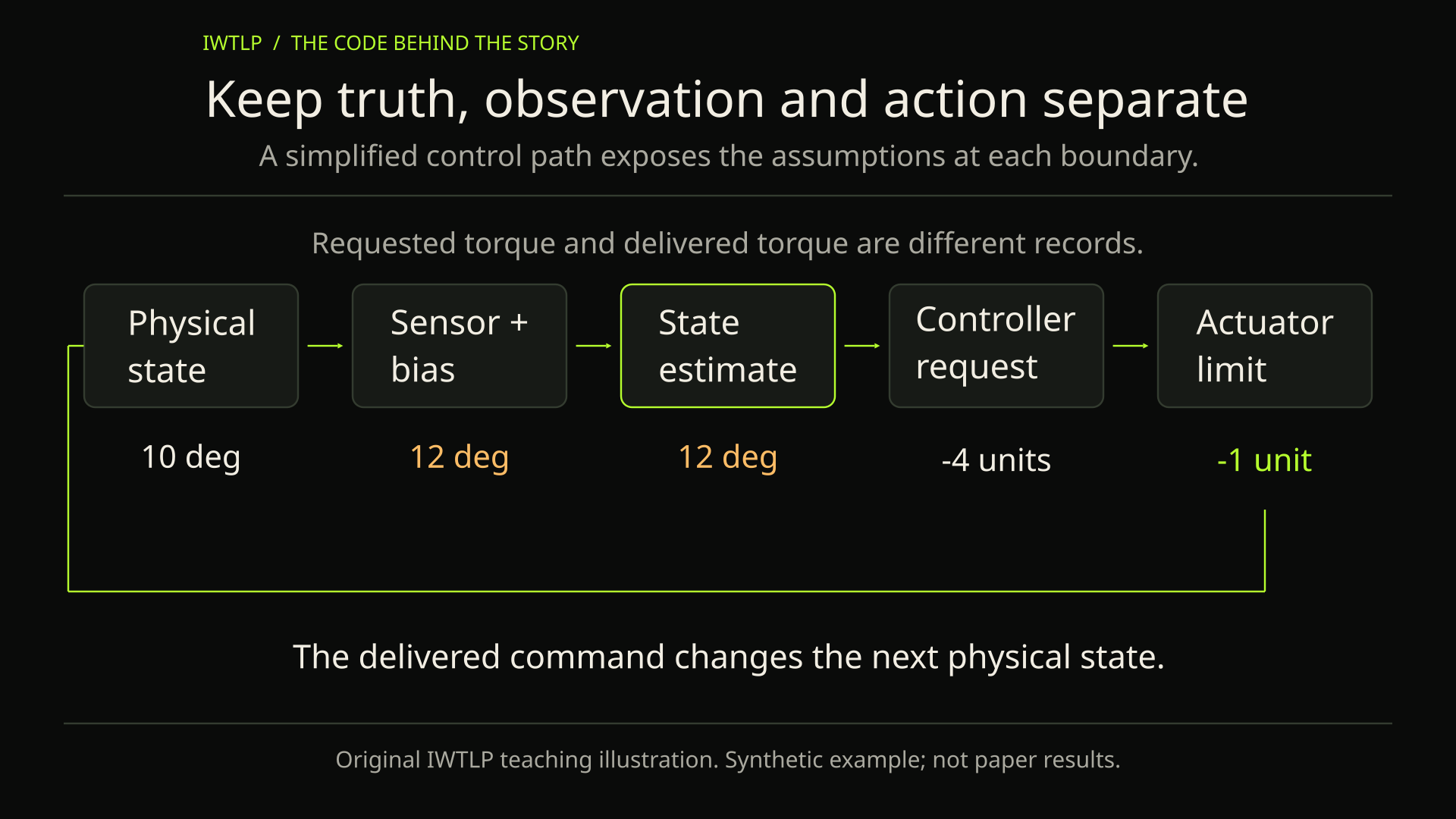
For an original teaching example, imagine a satellite that must rotate a camera by a small angle. Keep three records at every step: the simulated physical orientation, the sensor observation and the controller's estimate. Add a fixed offset only to the observation. If the code accidentally reads the physical state directly, the offset will have no effect. That absence is evidence about the wiring of the experiment, before it says anything about the quality of the controller.
Make the command path equally visible. The controller requests a torque; an actuator model decides what torque can be delivered; the simulated spacecraft responds. Recording both requested and delivered values exposes saturation. A small final pointing error does not tell you whether the controller spent the entire experiment demanding an impossible action. Those are different properties of the same run.
A configuration change should create a traceable experiment
The paper's architecture makes components replaceable through configuration. That is attractive when comparing spacecraft designs because it can reduce the amount of unrelated code changed between experiments. It still leaves a scientific responsibility: identify exactly which assumption changed and retain enough evidence to explain the new trajectory.
In our teaching example, hold the starting state, integration interval and disturbance sequence fixed while reducing the actuator limit. Compare the histories of pointing error and delivered torque. Then run a separate comparison with a sensor bias. Changing both together could be a useful combined test later, but it makes the first diagnosis harder. The point is to make the cause of a difference inspectable.
Store units beside the configuration. An angle in degrees and an angle in radians can both look like reasonable floating-point numbers. The simulator will happily compute with either unless the interface establishes what the value means. The same care belongs at boundaries between angular velocity, time and actuator commands. A tidy plot cannot rescue an experiment whose inputs meant different things to different components.
The useful result is a boundary you understand
There is a natural temptation to turn a successful simulation into a broad readiness claim. Keep the claim attached to the experiment instead: under these modeled conditions, this implementation produced these observations. Running a control loop on a small computer adds useful execution evidence, while real sensors, environmental effects and mission qualification introduce further questions.
For someone learning aerospace programming, a useful first result is a plot showing the requested turn, the measured turn and the action the hardware could deliver. When the lines disagree, you have a specific place to investigate. Start with one sensor and one actuator, then add complexity only when you can explain the simpler run.
Original source: McKeen, Scheuer and Cahoy / Research full text